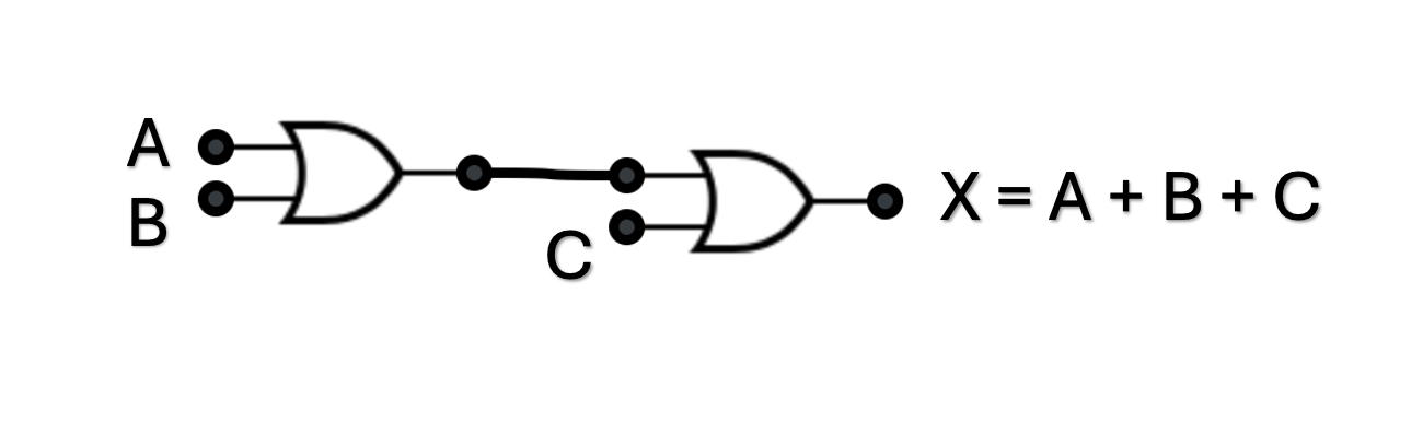
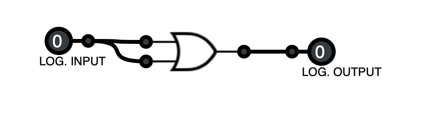
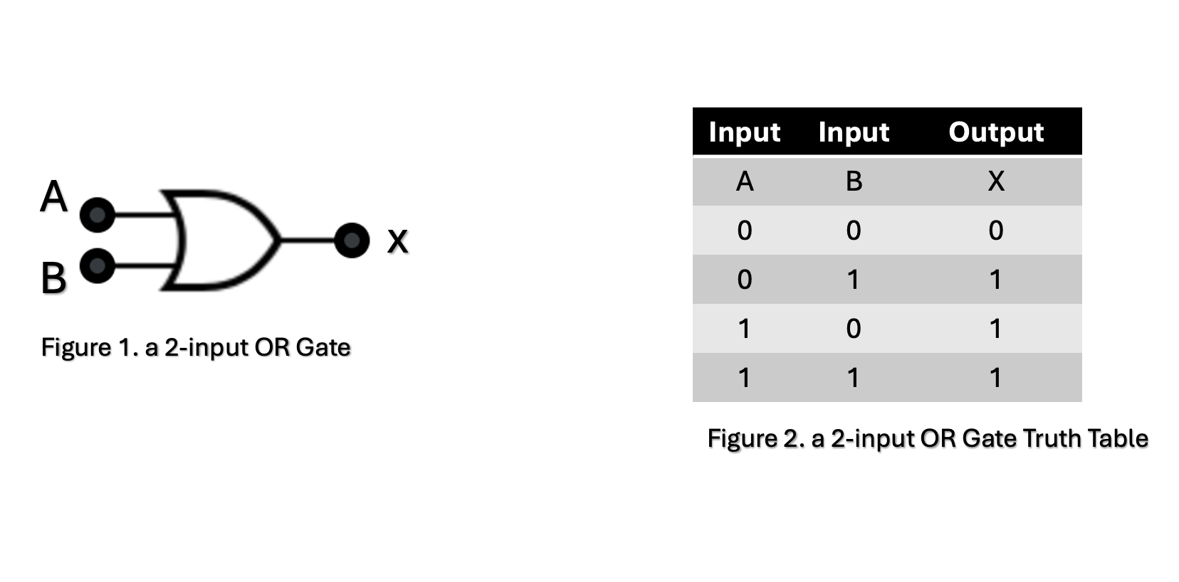
An OR gate is designed so that an output signal will occur any time there is an input signal. The presence of a signal is represented as logic 1 and the absence of a signal is represented as logic 0. A symbol for a two-input OR gate is shown in figure 1-1a.
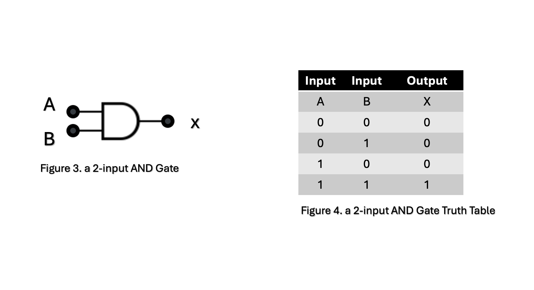
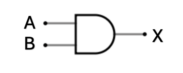
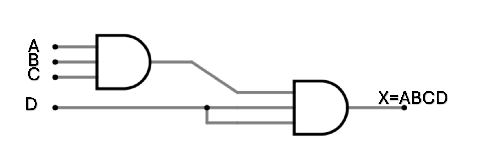
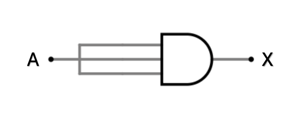
An **AND gate** is designed so that an output signal will occur only when there are signals at all inputs.
Inputs | Output | |
---|---|---|
A | B | |
0 | 0 | |
0 | +5 | |
+5 | 0 | |
+5 | +5 |
Inputs | Output | ||
---|---|---|---|
A | B | C | x |
0 | 0 | 0 | |
0 | 0 | +5 | |
0 | +5 | 0 | |
0 | +5 | +5 | |
+5 | 0 | 0 | |
+5 | 0 | +5 | |
+5 | +5 | 0 | |
+5 | +5 | +5 |
A | x |
---|---|
0 V dc | |
+5 V dc |
Input 1 | Input 2 | Output |
---|---|---|
0 | 0 | |
0 | +5 | |
+5 | 0 | |
+5 | +5 |
Inputs | Output | ||
---|---|---|---|
A | B | C | X |
0 | 0 | 0 | |
0 | 0 | +5 | |
0 | +5 | 0 | |
0 | +5 | +5 | |
+5 | 0 | 0 | |
+5 | 0 | +5 | |
+5 | +5 | 0 | |
+5 | +5 | +5 |
Inputs | Output | |||
---|---|---|---|---|
Input A | Input B | Input C | Input D | Output x |
0 | 0 | 0 | 0 | |
+5 | 0 | 0 | 0 | |
0 | +5 | 0 | 0 | |
+5 | +5 | 0 | 0 | |
0 | 0 | +5 | 0 | |
+5 | 0 | +5 | 0 | |
0 | +5 | +5 | 0 | |
+5 | +5 | +5 | 0 | |
0 | 0 | 0 | +5 | |
+5 | 0 | 0 | +5 | |
0 | +5 | 0 | +5 | |
+5 | +5 | 0 | +5 | |
0 | 0 | +5 | +5 | |
+5 | 0 | +5 | +5 | |
0 | +5 | +5 | +5 | |
+5 | +5 | +5 | +5 |
A | x |
---|---|
0 V dc | |
+5 V dc |